All About Probes
Bandwidth
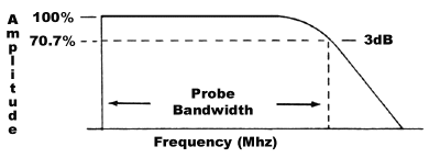
All oscilloscope probes are rated by bandwidth capability. Bandwidth is the point on an Amplitude versus Frequency curve, where the amplitude drops to less than 3 dB (70.7%) of its beginning low frequency amplitude.
Input Capacitance
Probe input capacitance is measured at the tip of the probe, using a BNC adapter ground sleeve. Many factors, such as short cable lengths, and higher attenuation ratios (10x & 100x) will provide low tip capacitance. A low input capacitance will reduce circuit loading, improve pulse amplitude measurements, and minimize rise time measurement errors. A quality 10x probe has 15 pF input capacitance or less.
Rise Time
Risetime is the time required for the leading edge of a pulse to rise 10% to 90% of its final value. Risetime is related to bandwidth by the following equation:

Attenuation
Most probes have an attenuation factor of 1x, 10x or 100x. A 10x probe has a total resistance of 9 meg ohms. When added to the 1 meg ohm resistance of the scope, the probe tip will have a 10 meg ohm resistance to ground.
Aberrations
Aberrations are deviations from the final top level of a step function. They are usually on the leading edge of a step function, and measured within the first 30 nanoseconds. Probe aberrations should be within the following limits.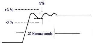
This specification basically states, that any aberration will not exceed +3% or -3% of final value or 5% peak to peak total aberrations.
Ground Lead Effect
A ground lead that is too long or is too high in inductance can cause ringing and may affect the quality of the signal being displayed. To reduce ringing in high frequency testing, use the shortest possible ground lead, and a probe with low input capacitance. Probe Master offers 3", 6" and 12" ground leads. Also available is a BNC adapter (PM4952BA) and a High Frequency Ground (PM4983HG).
Probe Compensation (Low Frequency)
A common oversight in making scope measurements, is forgetting to compensate the probe. Every probe should be low frequency compensated when attached to a scope for the first time. If not, distorted wave shapes may be observed on the scope display. The low frequency compensation procedure is as follows:
- Connect the probe tip to the scope calibrator. Most scopes provide a 1KHz square wave calibrator output.
- Switch the channel input coupling to DC.
- Turn on the scope and set the Volts/Div. switch to provide about four divisions of display.
- Set the sweep rate to 1m Sec./Div.
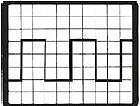
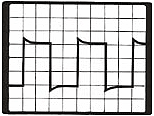
- Use the alignment trimmer tool to turn compensation adjustment until the tops and bottoms of the square wave are flat.
| Compensated | Over Compensated | Under Compensated |
 |
 |
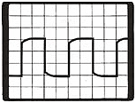 |
| 1 ms / div | 1 ms / div | 1 ms / div |
